
Step-by-Step Facial Image Acquisition Protocol
This section details the acquisition protocol described in our academic paper, organized into four parts. We start with the essential ethical considerations and IRB approval. The next section introduces the cameras set up, then we cover the capture system’s recording workflow, the standardized photos set up, and finalise with the 3D facial models acquisition device.
If you are interested in having access to the additional materials needed to replicate this setup at your institution – IRB forms, tripod adapter models, synchronization code, amongst others, – please request access filling the form at the bottom of the page . We can also provide support answering any questions that you might have regarding the acquisition protocol.
In the following sections we will describe the details on how the setup for facial image acquisition has been created and organized.
ETHICS COMMITTEE
This study was reviewed and approved by the Research Ethics Committee at University of Granada, under the certificate No.:4130/CEIH/202. As part of this agreement and to comply with the data protection laws, the identity of the participants the data collected is being pseudo-anonymized using unique ID codes to obscure personally identifiable information.
CAMERAS SETUP
Standardized facial photographs, CCTV recordings, and 3D facial models are collected at several designated locations, including both indoor and outdoor environments, in order to capture variations in lighting conditions. The video recording setup was designed to simulate typical identification scenarios encountered in forensic casework, such as images from public transport, ATMs, shops, or shopping malls. For this purpose, both consumer and commercial-grade cameras are used. In addition, a depth-sensor camera is included in the setup to provide subject-to-camera distance data. Facial photographs are then taken using a Digital Single-Lens Reflex (DSLR) camera positioned at a standardized distance from the participant. Three images are captured for each individual: one frontal and two lateral views (left and right). Finally, three-dimensional facial models are acquired using a specialized photogrammetry system, which captures the face from multiple angles and generates detailed models representing different facial expressions.
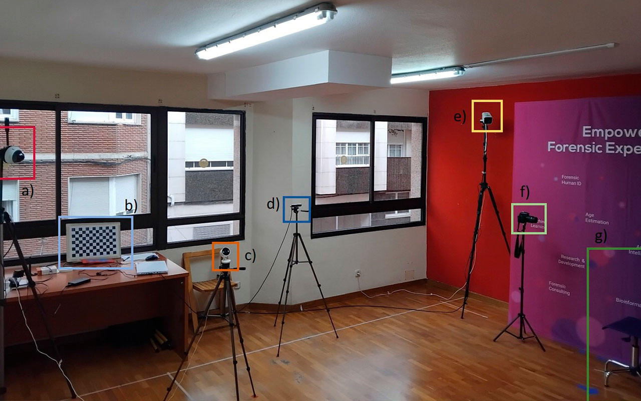
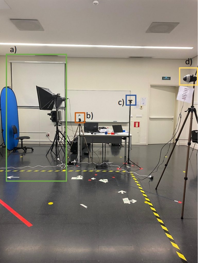
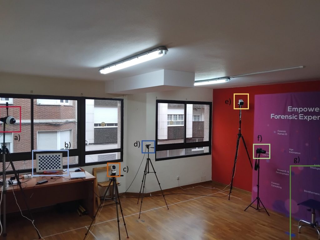
Figures 1 and 2 illustrate the configuration of the system at two different locations. Although the same cameras are used, their positioning varies depending on the environment, while ensuring that the depth sensor remains within the range of the other cameras. Table 1 summarizes the specifications for each of the acquisition devices, as well as other relevant information.
| Reference | Camera type | Specifications | Resolution | 2024 price | ||
| Focal length | FoV | CMOS | ||||
| Dahua DH-IPC-HDBW2831EP-S-0280B-S | Commercial surveillance camera | 2.8 mm | H: 105° V: 56° | 1/2.7” | 3840 x 2160 px | 160 € |
| Tapo C120 | Consumer camera | 3.17 mm | H: 103° V: 55° | 1/2.9” | 2560 × 1440 px | 40 € |
| Hikvision DS-2CD2046G2-IU | Commercial surveillance camera | 2.8 mm | H: 100.2º V: 54.7º | 1/3″ | 3840 x 2160 px | 250 € |
| Intel Realsense D455 | Depth Sensor | 1.93 mm | H: 90º V: 65º | 1/4″ OV 9782 | 1280 × 800 px | 540 € |
| Reference | Camera type | Focal length | ISO range | Resolution | Price range | |
| NIKON D-5200+NIKKOR 18-55mm f/3.5-5.6G II VR | DSLR Camera | 18–55 mm | 100–6400 | 6000 × 4000 px | 400-600€ | |
| DI4D SNAP 6200 | Photogrammetry system | Focal length and ISO range can be manually altered. Not specified | 24 mpx | 30,000 € (2017) | ||
VIDEO CAPTURE SYSTEM
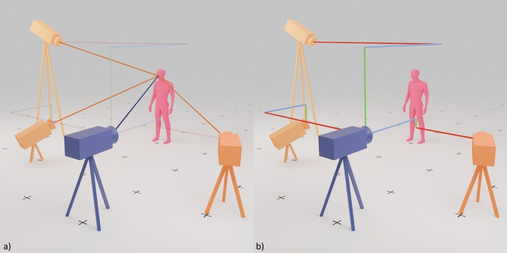
The video capture system is composed of three commercial CCTV cameras and a depth-sensor camera. These devices are placed at different heights and angles to reproduce conditions similar to those found in real surveillance environments. All cameras are synchronized so they record at the same time, allowing the subject to be captured from multiple viewpoints. The depth-sensor camera (Intel RealSense D455) acts as the reference point of the system. The other cameras are aligned relative to its central position, which serves as the origin of a shared coordinate system (x, y, z). Once the setup is calibrated, the position of each camera is defined in relation to this reference point. This configuration allows each CCTV camera to estimate the subject-to-camera distance (SCD) based on the subject’s position within the image.
The other cameras, the Hikvision DS-2CD2046G2-IU, Dahua DH-IPC-HDBW2831EP-S-0280B-S and Tapo C120, require a custom adapter to be mounted on a tripod. Any tripod capable of supporting 2–5 kg can be used, and extension tubes may be added to reach heights between 2 and 3 meters. The cameras are positioned at different heights to replicate common surveillance setups. The RealSense depth camera acts as the reference point of the system and should always remain within view of the subject throughout the recording and can be seen in figure 3. This is necessary to calculate the subject-to-camera distance (SCD) for the other cameras.
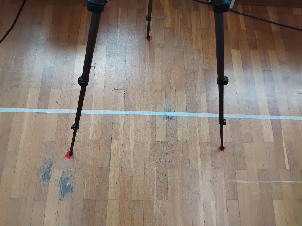
The placement of the cameras include positioning the Tapo C120 around 1.2–1.5 m (similar to an ATM camera), the Dahua dome camera around 1.5–1.8 m (slightly above eye level), and the bullet CCTV camera above 2 m, simulating standard surveillance in open spaces. Exact positioning may vary depending on the recording location. To ensure consistent data collection, tripod positions should be marked on the floor so cameras can be returned to the same location if moved, an example of this is shown in figure 4. While camera placement should remain consistent, recordings are intentionally captured under different lighting conditions, including both natural and artificial light, to better represent real-world scenarios.
Participants are asked to walk along a marked path toward the cameras while performing simple actions or expressions (such as answering a phone or speaking). Accessories like sunglasses, hats, or face masks may also be used to partially obscure the face, creating more varied and realistic data. Some examples of the marked pathway and the accessories are seen on figure 5.
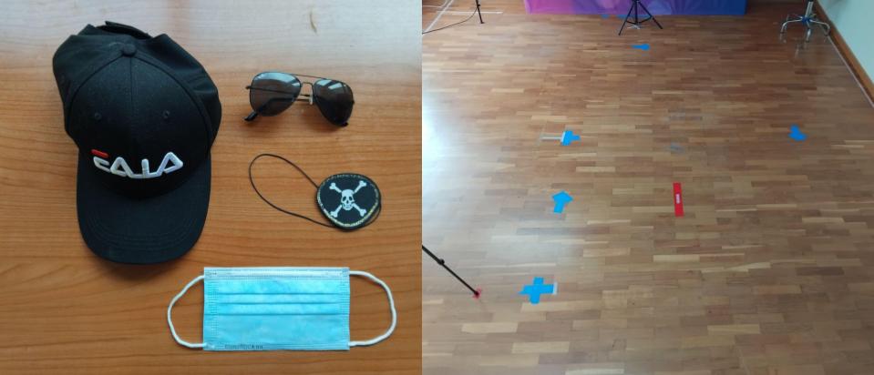
b) depicts the marks on the floor to instruct the subjects where to walk, the blue ones are the path, the red is where the subject is visible to all of the cameras.
All cameras are connected to a computer that controls and stores the recordings. The RealSense depth camera connects directly via USB 3.2, while the surveillance cameras connect through a wireless router. Although recordings are stored on the computer, each camera can also save footage to removable memory as a backup. The cameras can be synchronized using an 8×12 checkerboard pattern that acts as a visual clapperboard. For this to work, the cameras’ fields of view must overlap so the pattern is visible to all devices at the same time. The checkerboard can be displayed on a screen placed in the shared viewing area or briefly revealed by a person holding a printed pattern. The coordinate system is defined relative to the depth camera, meaning its orientation determines the orientation of the entire setup. If the depth camera observes a subject from behind while another camera captures them from the front, the measured depth value corresponds to the back of the head. As a result, the calculated subject-to-camera distance (SCD) will reflect that point rather than the face, which should be considered when positioning the cameras.
STANDARDIZED PHOTOS
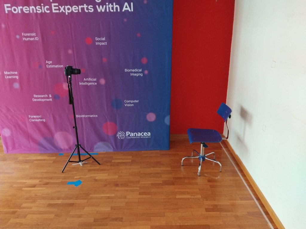
The next step in this process is capturing standardized facial photographs. For this purpose we located a tripod with the NIKON D-5200 with a AF-S DX NIKKOR 18-55mm f/3.5-5.6G II VR, 1.50-2m away from the subject, using a lens ranging from 18-55mm, adjusted to a 35mm focal. An adjustable chair was placed separate from the wall, to ensure that the height of the individual can be regulated and the face will always be in the center of the lens. It is recommended that both objects –the tripod and the chair– can be marked on the floor to ensure their consistent location. Figure 6 illustrates the placement of the camera and chair.
FACIAL 3D MODELS
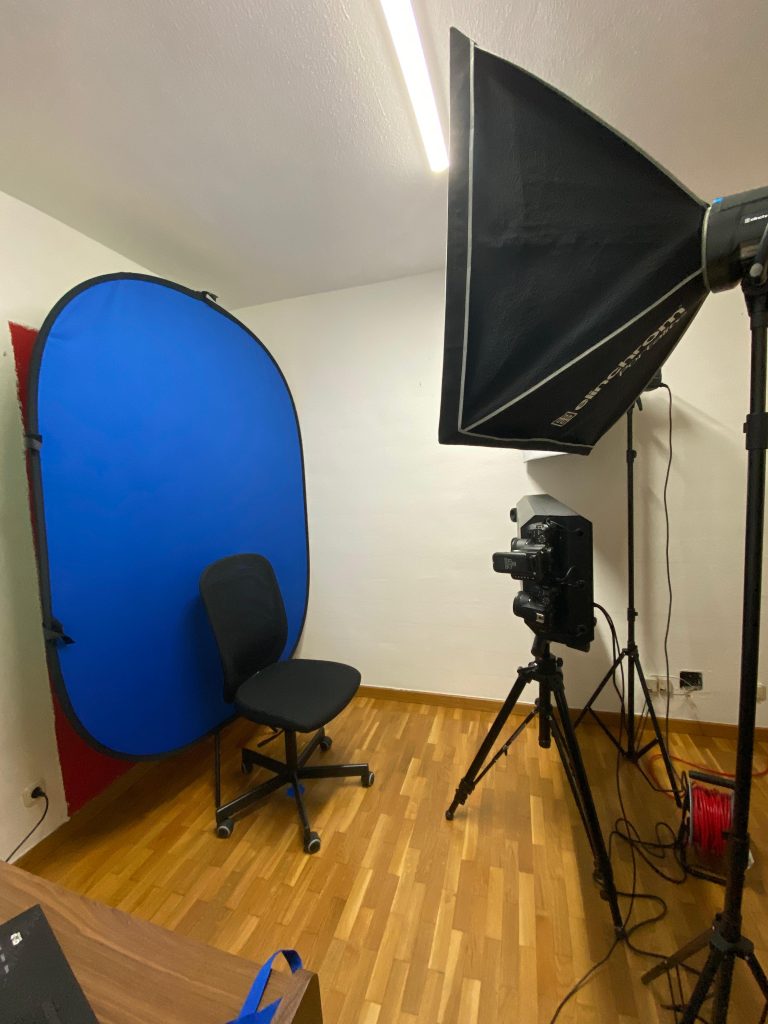
The last step of the circuit is the acquisition of the 3D facial model of different facial expressions (neutral, smile without teeth, smile with teeth, upset, angry and surprised) . For this purpose, a DI4D photogrammetry System is used. It is composed of six cameras that capture the face from different angles and through its own software a 3D realistic model with coloured texture can be processed. This setup also has two dedicated light sources to ensure uniform illumination, an example of how it is set up can be seen in figure 7, we were able to place it in a windowless room, it is recommended to locate the DI4D system in a place where light can be regulated. Participants should avoid any occluding objects, such as glasses, and should secure hair away from the face to prevent obstructions that could cause errors in model reconstruction. The chair used is also adjustable taking into consideration the height of the subject. Additionally, a uniform, solid-coloured background is required, and participants should avoid wearing clothes similar in colour to the backdrop, as this can interfere with accurate model generation.
ADDITIONAL MATERIAL
If you are interested in receiving additional materials for the implementation of this setup at your institution, you can request it by filling out this form.